
Weight sensor - 1kg (HX711)
Summary
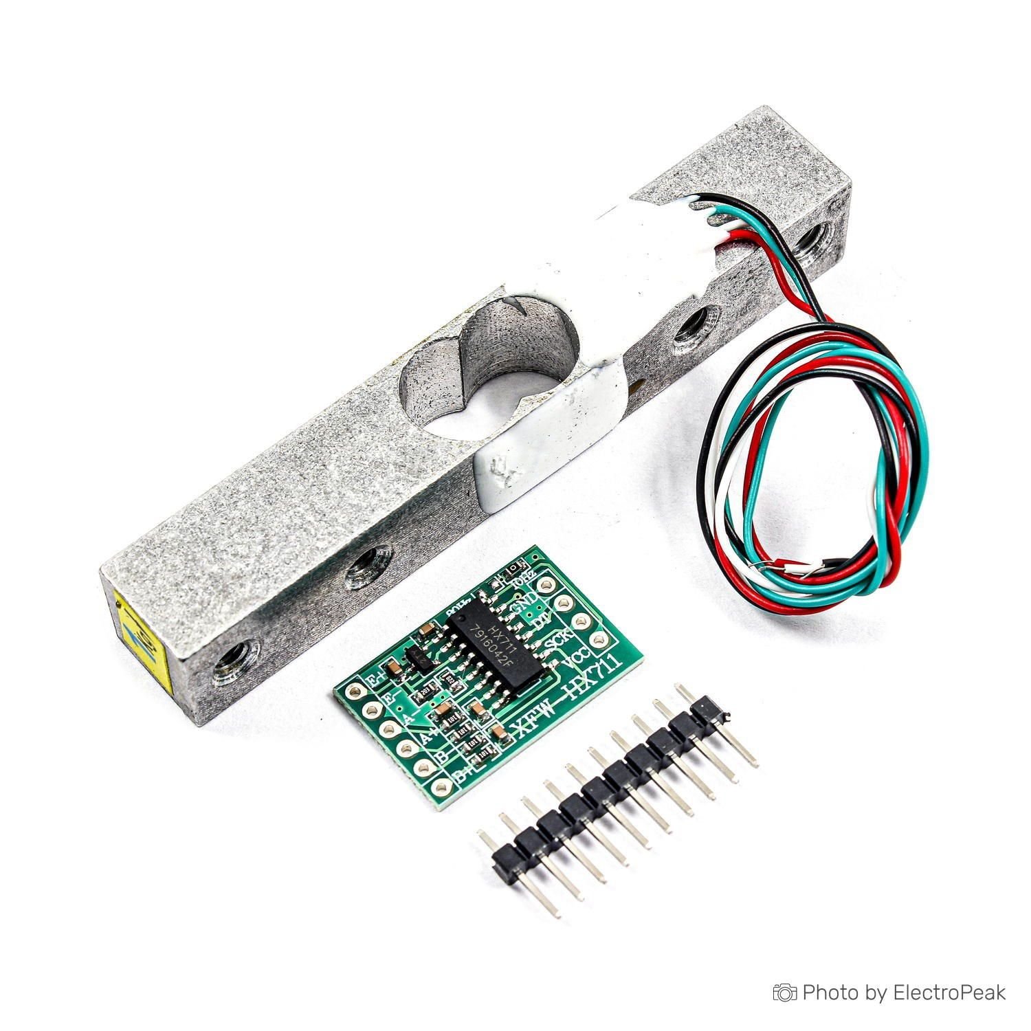
A load cell is a transducer that converts force into measurable electrical output. Load cells generally consist of a spring element on which strain gauges have been placed. The spring element is usually made of steel or aluminum. That means it is very sturdy but also minimally elastic. As the name "spring element" suggests, the steel is slightly deformed under load, but then returns to its starting position, responding elastically to every load.
Each straight bar load cell is made from an aluminum alloy and is capable of reading a capacity of 1Kg/2Kg/3Kg/5Kg/10Kg/20Kg. These load cells have four strain gauges that are hooked up in a Wheatstone bridge formation. Additionally, these load cells offer an IP65 protection rating and feature two M5 sized through-holes for mounting purposes.
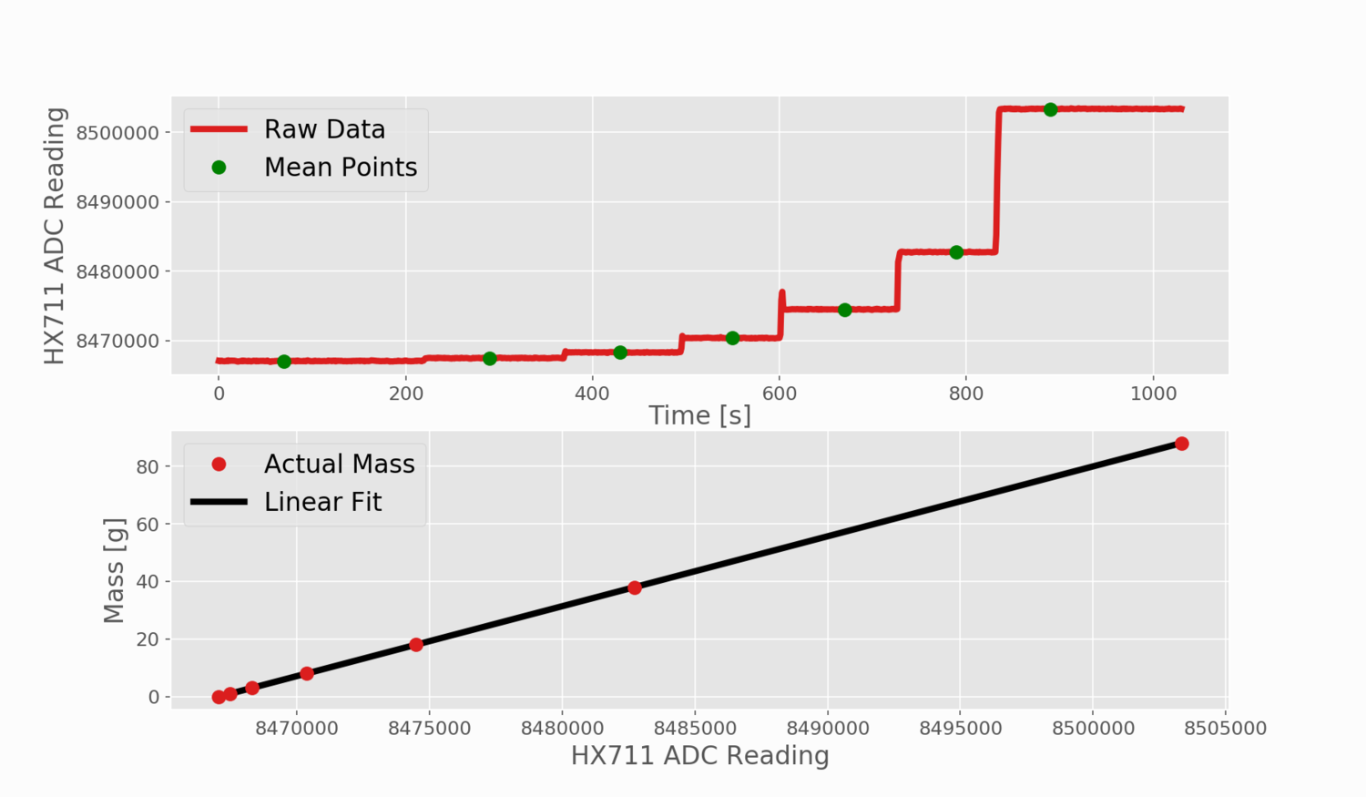
A load applied to a strain gauge triggers a change in resistance that can produce an output voltage proportional to the applied load. This relationship between strain and voltage can be used for calibrated weight measurement. Load cells are commonly used due to their linearity, cost effectiveness, and ease of implementation.
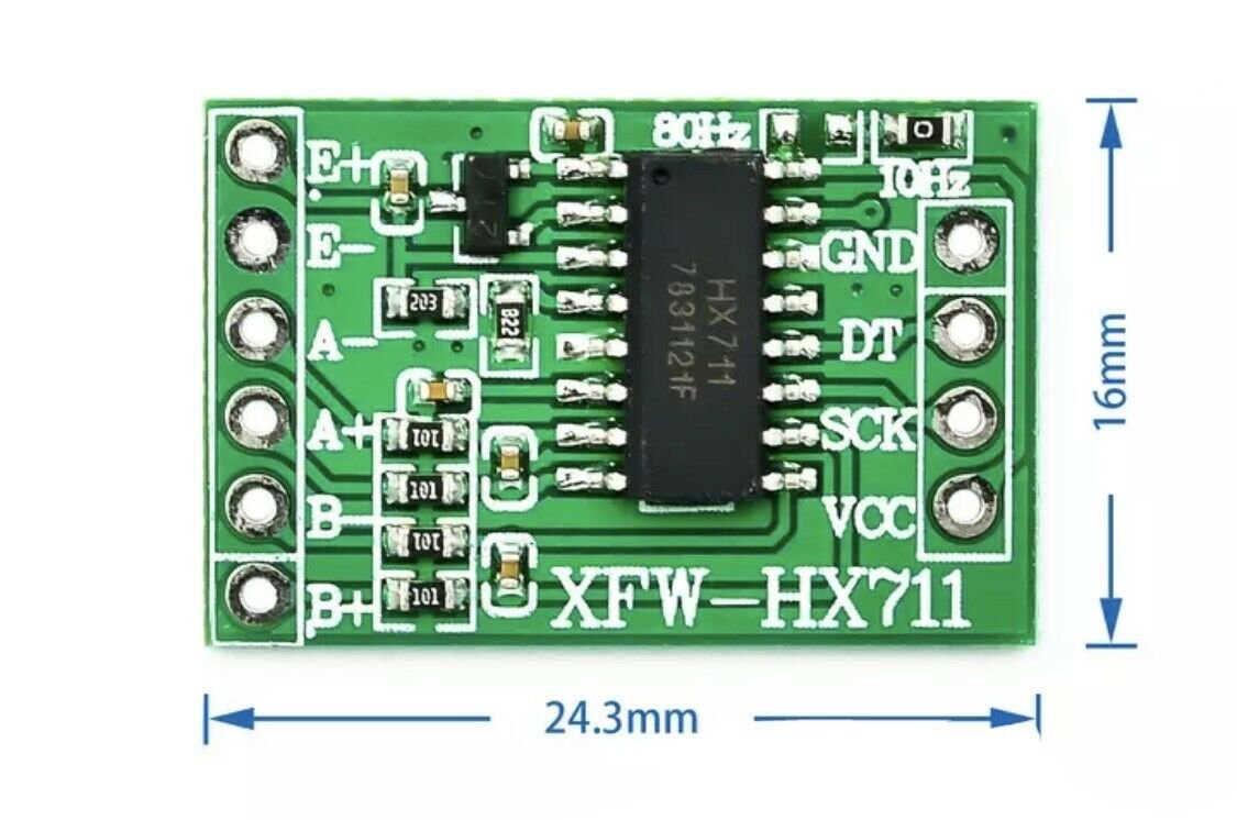
The HX711 is a 24-bit analog-to-digital converter translates the small changes in strain from the load cell into 24-bit changes in voltage (Arduino 0-5V). This allows the Arduino to resolve weight (mass) changes down to the range of the load cell (typically 500g, 1kg, 5kg, or more) divided by half the bit depth (2exp23). For a 1kg load cell, this results in mass change detection down to 0.0001g. In practice, however, the analog-to-digital converter and load cell both can have inherent noise (electrical and mechanical) which results in a much lower precision closer to 0.1% of the measurement value. The HX711 can be powered anywhere from 2.7V - 5.5V.
Load cell features:
Model: YZC-133, Rated Load: 1Kg, Rated Output: 1.0 0.15mV / V, Nonlinear: 0.03% F.S, Hysteresis: 0.03% F.S, Repeatability: 0.03% F.S, Creep (5 minutes): 0.05% F.S, Temperature Effect on Output: 0.003% F.S / C, Temperature Effect on Zero: 0.02% F.S / C, Zero Balance: 0.1000 mV / V, Input Impedance: 1066 ±20% Ω, Output Impedance: 1000 ±10% Ω, Insulation Resistance: 2000 MΩ, Recommended Operating Voltage: 5V, Maximum Operating Voltage: 10V, Material: Aluminum
How to Connect
To connect to the Grove board:
1. Connect the red wire to the E+ and the black wire to the E- output of the HX711 module.
We chose the red and black wire pair to be the power wires of the load cell. E+ and E- are the sensor power outputs of the HX711 module. The polarity doesn't matter. We picked red to be the positive side and black to be the negative side to make it follow a common convention. Switching up red and black will only invert the calibration parameter in the software.
2. Connect the green wire to the A+ and the white one to the A- inputs of the HX711 module
A+ and A- are the measurement inputs of the HX711 module. Like with the power wires, the polarity is not important. You just need to recalibrate in the software if you switch them up.
3. Connect the GND of the HX711 module to the Arduino GND and VCC to the Arduino 5V pin.
HX711 also works with 3.3V. If you have some other microcontroller that runs on 3.3V, you can use 3.3V instead of 5V.
4. Connect the DT and SCK of the HX711 module to any of the Arduino digital IO pins.
In the schematic, I used pins 4 and 5, since those are the default pins for the examples of the "HX711_ADC" library. If you want to use interrupts to update scale data, then you should connect the DT output to an interrupt enabled pin of the Arduino. For Uno/Nano, those are pins 2 and 3.


How to use in XOD


The load cell needs to be mounted in a way that allows a supported weight to apply a direct lateral force. There are a number of designs for 3D printed stands that can be adapted for the provided load cells.


3D printed mounts to support load cells: https://www.thingiverse.com/thing:3129439 and https://www.prusaprinters.org/prints/32094-load-cell-mount
Notes
Source of item: https://www.aliexpress.com/item/1005001418508621.html
Arduino Weighing Scale with Load Cell and HX711: https://makersportal.com/blog/2019/5/12/arduino-weighing-scale-with-load-cell-and-hx711
How load cells work: https://www.anyload.com/load-cell-force-transducer-how-it-works/
Getting Started with Load Cells: https://learn.sparkfun.com/tutorials/getting-started-with-load-cells