

Looking to get started? Join one of our workshops or grab self-learning materials!
Stage-1: No-code programming for beginners
The No-Code Programming for Biology programme has been designed by the Biomaker team to introduce beginners to the basics of building hardware and bioinstrumentation. The first stage of training is accessible to anyone - no existing knowledge is required.
The programme is designed to introduce biologists, or other scientists with little formal programming training, to the basics of Biomaking, including:
● Use of Arduino-based microcontrollers
● Use of sensors, displays and actuators
● Use of XOD visual programming
Training in the use of these new tools will allow participants to build a wide range of instruments and devices that are potentially useful for experiments in the lab and field. These new skills can be enabling in many ways. The components for this type of instrumentation are often very cheap, especially when compared with off- the-shelf commercial solutions. The use of simple hardware and software resources allow easy modification, extension and repair of custom instruments. The use of open-source components and systems promotes sharing of information and set up of collaborative projects, which creates a growing set of resources for the community to draw from.
A free Beginner's guide provides instructions on how to setup a simple microcontroller board (the Grove Beginner Kit from Seeed Studio) with the XOD graphical programming environment, and a step-by-step guide to using hardware components on the board. These include a variey of sensors, input and output devices. This provides the basic skills required to build custom instruments for use in biological lab and fieldwork.
The Grove Beginner Kit is relatively low-cost and easy to obtain; XOD is open-source and free; the Biomaker Beginner’s Guide is currently available in English and Spanish language versions. Training can be run as a self-taught exercise, or though participation in online or in-person tutorial sessions.
Biomaker also runs regular Challenges, where teams can apply for funding to pursue a extended projects. You can find examples of previous Biomaker projects covering a wide range of applications including instrumentation, microscopy, microfluidics, 3D printing, biomedical devices, DNA design, plant sciences and outreach and public engagement under the Projects tab.


Software: XOD for visual programming
XOD is open source software development environment that can be used to programme the Arduino microcontroller board. It uses a graphical interface that represents hardware and computing elements as nodes that can be wired together to allow data flow between the objects. XOD allows a hierarchical and dataflow driven approach, avoids the complexities of text management and syntax, and can be used to directly programme Arduino boards. We think that this provides a simple way for non-programmers (i.e. biologists) to develop useful skills and understanding - without needing to deal with the complications of programming languages and syntax. We have chosen XOD as an accessible tool for Biomaker training and device development. The software can be downloaded from: (https://xod.io).
The XOD IDE (Integrated Development Environment) available in two different formats, a desktop client and a web-based client that you run in your browser. We generally use the desktop IDE. Both implementations have similar appearance and functionality, but the desktop version allows compilation on a local computer without quota limitations. There are versions of the desktop IDE for Windows, Mac OSX and Linux.
The XOD interactive development environment
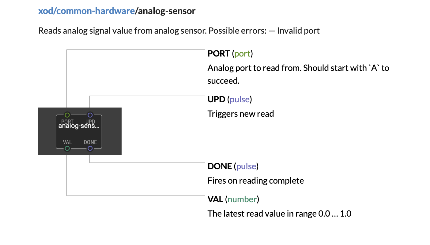
This introductory project provides a series of tutorial “patches” (see below). A patch is the working area for a XOD program. It is similar to a “sketch” in the Arduino IDE, but instead of text code - the patch is built with “nodes”, which are the basic elements in a XOD program. A node can represent many different things: an electronic component like an LED, a sensor like the LM75 temperature sensor, a logic function like AND, OR or NOR, a pulse source like a Square Wave or Sine Wave generator, a mathematical function like multiplication or addition, a conversion function like metres to feet or a Boolean function. Each node is represented by a rectangular box that has one or more circular connections on the top and bottom. These connectors are called “pins”.
“Input pins” are located on the top side of each node, while those on the bottom are “output pins”. The pins on a node are like variables and can contain parameter values. The values can be left at their default values, or selected and set using the “Inspector”, or receive new values via connection to the output pins of other nodes.
Image from: https://forum.arduino.cc/index.php?topic=572630.0
The pins on a node can have different data types, represented by colors.
Green Pins represent numbers.
Blue pins represent pulses.
Violet pins represent boolean values.
Orange pins represent strings.
XOD nodes
A XOD program consists of nodes connected together in one or more patches. New nodes are selected in the Project Browser, and dragged onto the patch area. If you know the name of the node you want to add, you can double-click on a blank area of the patch or press the ”i” key on your keyboard. This will bring up a search box where you can type in the name of the relevant node. If the search is successful, highlight the node in the results and hit “enter” to put the node onto the patch.
In XOD “Links” are the lines used to connect nodes to each other. A link runs from an output pin on one node to the input pin on another node.
You create a link by clicking on a pin on one node, this created the starting point of the link. You then drag it to another pin on another node. You can start creating a link by clicking on either an input or an output pin.
XOD is smart and won’t let you link a pin to another pin if it doesn’t make sense or if the data types are incompatible. The link color is determined by the data type of the output pin in the link.
Linking nodes is a lot like wiring elements in an electronic circuit. In fact a XOD program really looks more like a wiring diagram than anything else.
XOD Forum
If you are having difficulty with any issue, please visit the XOD website (https://xod.io) which contains tutorial material and the XOD Forum. There is a new section of the forum dedicated to Biomaker (https://forum.xod.io/c/biomaker/13), which will allow you to tap into the collective expertise of the XOD community - and which we will monitor also. The forum is great source of useful information and news about newly released libraries, and is highly recommended as a source of collected information about XOD.

Hardware: the Grove Beginner Kit
Port connections:
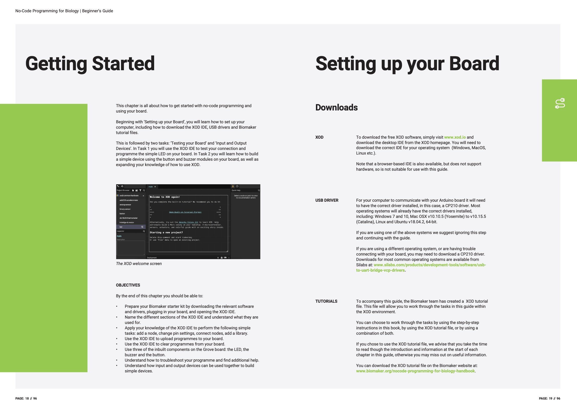
Setting up your Board
Download the XOD development software.
To download the free XOD software, simply visit www.xod.io and download the desktop IDE from the XOD homepage. You will need to download the correct IDE for your operating system (Windows, MacOS, Linux etc.).
Note that a browser-based IDE is also available, but does not support hardware, so is not suitable for use with this guide.
2. Ensure that the USB driver is installed
For your computer to communicate with your Arduino board it will need to have the correct driver installed, in this case, a CP210 driver. Most operating systems will already have the correct drivers installed, including: Windows 7 and 10, Mac OSX v10.10.5 (Yosemite) to v10.15.5 (Catalina), Linux and Ubuntu v18.04.2, 64-bit. If you are using one of the above systems we suggest ignoring this step and continuing to test communicationj between XOD and the board.
If you are using a different operating system, or are having trouble connecting with your board, you may need to download a CP210 driver. Downloads for most common operating systems are available from Silabs at: www.silabs.com/products/development-tools/software/usb- to-uart-bridge-vcp-drivers.
3. Install the XOD tutorial file
To accompany this guide, the Biomaker team has created a XOD tutorial file. This file will allow you to work through the tasks in this guide within the XOD environment.
You can choose to work through the tasks by following the step-by-step instructions in the Biomaker Handbook, entering detail manually, or by using the pre-assembled XOD tutorial file, or by using a combination of both. If you chose to use the XOD tutorial file, we advise that you take the time to read though the introduction and information at the start of each chapter in this guide, otherwise you may miss out on useful information.
You can download the XOD tutorial file on this website (also linked from the resources pages).
4. Test the connection with the board
Assemble a simple XOD program (e.g. to flash the onboard LED at a certain rate) and upload this to the board. Check that the program is uploaded without error messages, and is functional. More complete instructions can be found in the following extract from the Biomaker handbook. Click the image to download.
Click to download instructions as a PDF
XOD nodes for the hardware on the Grove Beginner Kit
The Grove Beginner Kit consists of a central microcontroller on an Arduino-compatible board linked to a series of ten different components on surrounding parts of the circuit board. Within the intact board, copper traces allow the microcontroller to communicate with the components via ports indicated above. (If needed, the individual component daughter boards can be cut from the host, and used as individual modules, wired via the white-coloured Grove connectors. “Grove” refers to the plug standard used for interconnection of the different digital, analogue, SPI, serial and I2C connections.)
Different XOD nodes from the standard XOD installation, and from external libraries, can be used to control the different peripheral components. These are shown below:
1. LED

2. Buzzer

The piezo can be connected to digital outputs and will emit a tone when the output is high. Alternatively, it can be connected to an analog pulse-width modulation output to generate various tones and effects.
3. OLED

The OLED Display 0.96" (SSD1306) is a monochrome(white) 128×64 pixels display matrix module with I2C Interface.
External XOD library
wayland/ssd1306-oled-i2c@0.0.7
Arduino library for OLED displays driven by the SSD1306 chip. Communication via I2C. Wraps Adafruit_SSD1306 (https://github.com/adafruit/Adafruit_SSD1306).
clear-display: Clear contents of display buffer (set all pixels to off). Changes buffer contents only, no immediate effect on display. Follow up with a call to send-buffer-to-display, or with other graphics commands as needed by one's own application.
dim-display: Dim display. This has an immediate effect on the display, no need to use the send-buffer-to-display node -- buffer contents are not changed.
draw-circle: Draw a circle. Writes data to display buffer. To show content of display buffer on screen use node send-buffer-to-display.
draw-line: Draw a line. Data written to display buffer. To show content of display buffer on screen use node send-buffer-to-display.
draw-pixel: Draw a pixel.
draw-rectangle: Draw a rectangle. Writes data to display buffer. To show content of display buffer on screen use node send-buffer-to-display.
draw-rounded-rectangle: Draw a rounded rectangle. Writes data to display buffer. To show content of display buffer on screen use node send-buffer-to-display.
draw-text: Writes string to display buffer. To show content of display buffer on screen use node send-buffer-to-display.
draw-triangle: Draw a triangle. Writes data to display buffer. To show content of display buffer on screen use node send-buffer-to-display.
draw-xod-logo: Draw XOD logo. Logo is 128 x 64 pixels.
example-draw-shapes: Draw shapes in proportion to display size.
example-rotate-display: Text will be drawn in two different directions.
example-scroll: Performs a diagonal right scroll for 30 seconds, then stops scrolling.
example-xod-logo: Display and inversion of XOD logo.
get-display-dimensions: Get dimensions of display in pixels.
invert-display: Enable or disable display invert mode (white-on-black vs black-on-white). This has an immediate effect on the display, no need to use the send-buffer-to-display node -- buffer contents are not changed, rather a different pixel mode of the display hardware is used. When enabled, drawing BLACK (value 0) pixels will actually draw white, WHITE (value 1) will draw black.
rotate-display: No description
send-buffer-to-display: Push data currently in RAM to SSD1306 display. Drawing operations are not visible until this function is called. Call after each graphics command, or after a whole set of graphics commands, as best needed by one's own application.
ssd1306-oled-i2c-device: Create SSD1306 OLED device.
start-scroll: Activate scroll for all or part of the display. To scroll whole display set FIRST to 00h and LAST to 0Fh.
stop-scroll: Stop scrolling.


4. Button

The Grove Button is a momentary push button. It contains one independent "momentary on/off" button. “Momentary” means that the button rebounds on its own after it is released. The button outputs a HIGH signal when pressed, and LOW when released.

5. Potentiometer
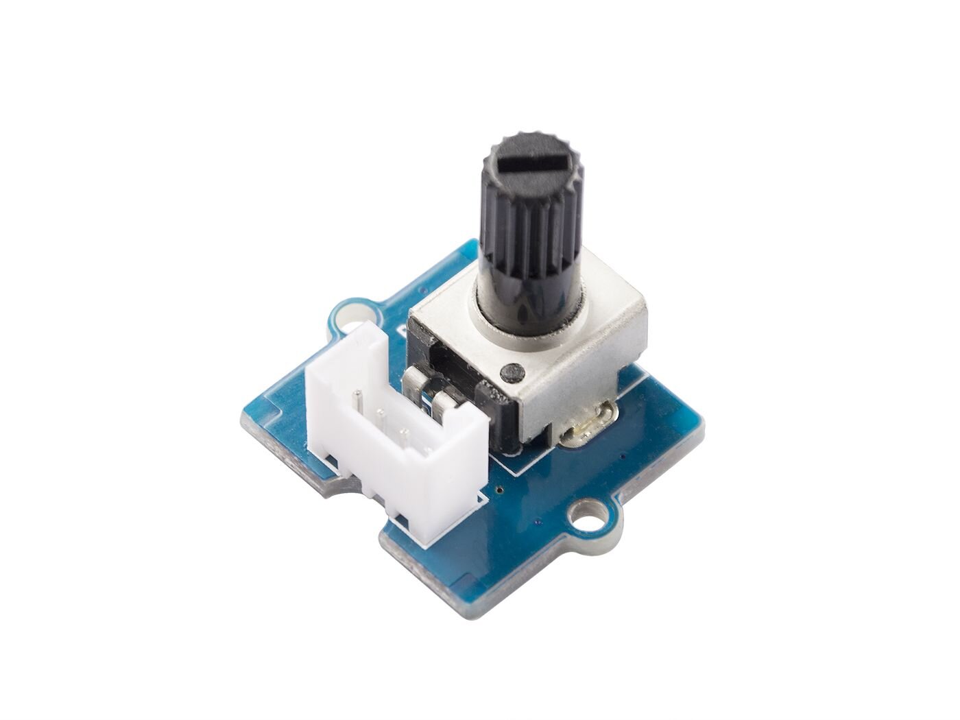
The potentiometer or pot, consists of an internal resistive element called the track and a sliding contact called the wiper where end terminals are attached to the resistive element. These allow the output of a variable voltage that is converted to an output value of 0 to 1.

6. Light sensor
The Grove - Light sensor integrates an LS06-S photo-resistor (light dependent resistor) to detect the intensity of light. The resistance of photo-resistor decreases when the intensity of light increases. A dual OpAmp chip LM358 on board produces voltage corresponding to the intensity of light (i.e. based on resistance value). The output signal is analog value, the brighter the light is, the larger the value, with a short response time: 20 ~ 30 milliseconds.
External XOD library
wayland/analog-read-no-port-check
The device is connected to analog port 6 on the Beginner board. This is usually not connected on Arduino UNO compatible boards, so you should use a custom analog read node that has been written by Matt Wayland (https://xod.io/libs/wayland/analog-read-no-port-check/). This allows the output voltage of the sensor to be converted to a digital signal by the analog-to-digital-converter on your controller board.

7. Sound sensor

Grove - Sound Sensor can detect the sound intensity of the environment. The main component of the module is a simple microphone, which is based on the L358 amplifier and an electret microphone. This module's output is analog and can be easily sampled and tested by an Arduino microcontroller.
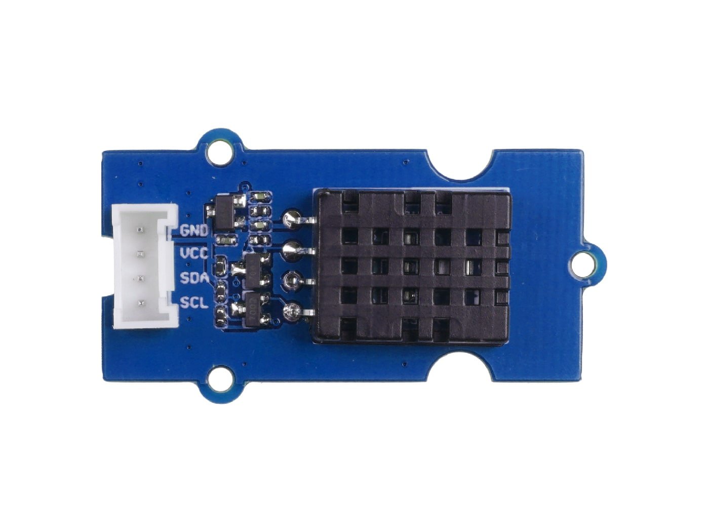
8. DHT11 or DHT20 Hygrometer
Please note that Seeedstudio supply different version of the Grove Beginner’s board with either the DHT11 (blue coloured) or the DHT20 (black coloured). These devices are similar in function, but required different nodes and communication routines!

DHT11
Grove - DHT11 Temperature & Humidity Sensor is a high quality, low-cost digital temperature, and humidity sensor based on the DHT11 module.
DHT11 is the most common temperature and humidity module for Arduino and Raspberry Pi. It is widely favored by hardware enthusiasts for its many advantages such as low power consumption and excellent long-term stability. Relatively high measurement accuracy can be obtained at a very low cost. The single-bus digital signal is output through the built-in ADC, which saves the I/O resources of the control board.
The Grove - Temperature & Humidity Sensor uses an upgraded version of DHT11. The new version of the DHT11 module replaces resistive humidity components with capacitive humidity components. The temperature and humidity measurement range are wider. The temperature resolution is higher.
External XOD library
xod-dev/dht@0.36.1
Nodes to work with DHT11 or DHT21 sensors, or compatible sensors: RHT01, DHT22, DHT33, DHT44, AM2301, HM2301, AM2302, AM2303, RHT02, RHT03, RHT04, RHT05.
XOD Nodes
dht11-device: Represents a DHT11 sensor. Also named RHT01.
dht11-hygrometer: Read the temperature and humidity by the DHT11 (RHT01) hygrometer sensor.
dht2x-device: Represents a DHT21 or compatible sensor: DHT21, DHT22, DHT33, DHT44, AM2301, HM2301, AM2302, AM2303, RHT02, RHT03, RHT04, RHT05.
dht2x-hygrometer: Read the temperature and humidity by the DHT21 or compatible (DHT21, DHT22, DHT33, DHT44, AM2301, HM2301, AM2302, AM2303, RHT02, RHT03, RHT04, RHT05) hygrometer sensor.
example-dht11: No description
read: Reads the temperature and humidity.
read(dht11-device): Reads the temperature and humidity.
read(dht2x-device): Reads the temperature and humidity.


DHT20
The newer Grove - Temperature & Humidity Sensor is based on the DHT20 sensor. The DHT20 is an upgraded version of the DHT11, compared with the previous version, the temperature and humidity measurement accuracy are higher, and the measurement range is larger. It features I2C output.
External XOD library
wayland/dht20@0.0.3
ASAIR DHT20 humidity and temperature sensor (https://cdn-shop.adafruit.com/product-files/5183/5193_DHT20.pdf). Wraps https://github.com/RobTillaart/DHT20
NodeDescription
init: Initialize dht20-device.
dht20-device: Create a dht20-device.
read: Measure relative humidity and temperature.
example: Patch for testing sensor. Run in debug mode.
hygrometer-thermometer: Combines lower level nodes to create a ready to use sensor.


9. Air pressure sensor
Description
The Grove BMP280 Barometer Sensor is built around Bosch BMP280, it is a low-cost and high-precision environmental sensor that measures the temperature and air pressure. This sensor supports both I2C and SPI communication using a custom BMP280 Arduino library.
Grove BMP280 provides precise measurements of barometric pressure and temperature in the environment. The air pressure can be measured in a range from 300 hPa to 1100hPa with ±1.0 hPa absolute accuracy. It also provides a temperature readout, for temperatures between - 40℃ and 85℃ with an accuracy of ±1℃.
Owing to its high accuracy in measuring air pressure, and known pressure changes with altitude, one can calculate the altitude with ±1 meter accuracy, which makes it a precise altimeter as well. It provides both I2C and SPI interfaces for communication with the microcontroller. The board provides alternative I2C addresses.
https://ae-bst.resource.bosch.com/media/_tech/media/datasheets/BST-BMP280-DS001.pdf
External XOD library
wayland/bmp280-barometer@0.0.1
Library authored by Matt Wayland for the BMP280 barometric pressure and temperature sensor. Converted from https://github.com/adafruit/Adafruit_BMP280_Library.
bmp280-device: Create BMP280 device. See datasheet (https://ae-bst.resource.bosch.com/media/_tech/media/datasheets/BST-BMP280-DS001.pdf) for recommended oversampling and filter settings for specific use cases.
calculate-altitude: Calculate altitude from atmospheric pressure.
read-pressure: Read pressure in Pascal.
read-temperature: Read temperature in degrees Celsius.
example-oled-altimeter: Uses bmp280 as an altimeter and displays altitude on an OLED screen.
barometer-thermometer: Combines low level nodes to create a simple to use barometer and thermometer.
example-test-barometer-thermometer: Patch to test barometer-thermometer node. Run in debugger.


10. LIS3DHTR accelerometer
Description
The Grove 3-Axis Digital Accelerometer contains a low-cost 3 axis accelerometer (LIS3DHTR). It is based on the LIS3DHTR chip which provides multiple measurement ranges: ±2g, ±4g, ±8g, ±16g. The tiny 3 - Axis accelerometer can support I2C, SPI, and ADC GPIO interfaces, which means you can choose any way to connect with your development board. In addition, this accelerometer can also be temperature compensated to tune the errors.
External XOD library
wayland/lis3dh-accelerometer@0.0.1
Authored by Matt Wayland to support the LIS3DH triaxial accelerometer. Wraps https://github.com/adafruit/Adafruit_LIS3DH.
accelerometer: Combines lower level nodes to create a simple to use accelerometer.
click-detector: Combines low level nodes to create a simple to use click-detector. Detects single or double taps of the sensor.
example-read-adc: Patch to test read-adc node. Run in debugger.
example-read-raw: Patch to test read-raw node. Run in debugger.
get-click: Detect single or double "click" (tap).
get-data-rate: Get data rate.
get-device-id: Read the ID of the lis3dh device.
get-range: Read the g range for the accelerometer.
lis3dh-device: Create a lis3dh device.
read-acceleration: Read acceleration (metre per second squared) in all three axes.
read-adc: Read the auxiliary analog-to-digital converter.
read-raw: Read X, Y and Z raw values.
set-click: Configure parameters for "click" (tap) detection. See datasheet for explanation of parameters: http://www.st.com/resource/en/application_note/cd00290365.pdf
set-data-rate: Set data rate.
set-range: Set range.
example-motion-detector: Demonstrates how lis3dh can be used as a motion sensor. LED is illuminated if motion is detected. Push button resets motion detector.
example-test-accelerometer: Test of accelerometer. Run in debugger.
example-test-click-detector: Test of click-detector. Run in debugger.
example-tweak-settings: Demonstrates changing data-rate and range at runtime using tweak nodes. Run in debugger.


11. Microcontroller board
The Grove Beginner’s kit contains an embedded microcontroller board that is based on the Seeeduino Lotus ATMEGA328 development board. It is a combination of Seeeduino and Base Shield. The Seeeduino Lotus v1.1 uses a high performance, low power AVR 8-Bit Atmel ATMEGA328P-MU chip and Silicon Labs CP2102N USB-to-serial interface chip for laptop communication. The Seeeduino Lotus has 14 digital input/outputs (6 of which can output PWM) and 7 analog input/outputs, a micro USB connection, an ICSP header, 12 Grove connections, a reset button. More information about the component can be found on the Seeed Studio wiki site:
https://wiki.seeedstudio.com/Seeeduino_Lotus/
