
Plug and play synthetic biology education resource
We want to develop a prototype teaching resource that allows audiences to learn about synthetic biology in a hands on way.
The Idea
We aim to bring together an interdisciplinary team of biologists and engineers to develop a plug and play system of physical blocks representing the building components of a genetic circuit which will encourage audiences to learn about physical genetic circuits. The idea is that these example circuits would then be built in the labs at the Cambridge Biomakespace, using pre-existing plasmids where possible. The prototype resources will be tested by the Biomakespace, London Hackspace members and will be used as teaching aids in workshops in and beyond Biomakespace. This project will allow Biomakespace to realise one of its objectives - to teach synthetic Biology to Biomakespace members. Biomakespace will approach organisations that may be interested in using the resources for their key audiences. In the future, Biomakespace may explore running a competition, inviting people to design new genetic circuits and the winning circuit could get synthesized and built in the lab.
The Team


Dr Payam Mehrshahi,
Postdoctoral researcher, Department of Plant Sciences, University of Cambridge
Dr Katia Smith-Litière,
Co-founder at Cambridge Science Centre, Cambridge Biomakespace
Mr Patrick Hickland,
Graduate student, Department of Plant Sciences, University of Cambridge
Mr Marek Balint,
Sofware engineer at Repositive; Cambridge Biomakespace
Mr Tony Naggs,
Cambridge Biomakespace
Mr Roger Mason,
Director of NDimensions Ltd, Cambridge Biomakespace
Project Outputs

Project Report
SUMMARY OF THE PROJECT'S ACHIEVEMENTS AND FUTURE PLANS

Project Proposal
Original proposal and application

Project Resources
Progress on the development of a plug and play synthetic biology educational resource
Summary
We set out to develop a prototype teaching resource that will encourage audiences to learn about genetic circuits in a hands on way, providing them with knowledge of the concepts of synthetic biology and the confidence to participate in multidisciplinary synthetic biology research projects at Biomakespace. We brought together an interdisciplinary team of biologists, software and electronic engineers with the aim to develop a plug and play system of physical blocks representing the building components of a genetic circuit. A secondary aim was for the biologists and the engineers to develop an understanding of each other’s approach to design requirements of “physical” and “Biological” hardware. To date, we have identified a suitable example of a simple circuit and have obtained a plasmid with the biological components and permission to use this for educational purposes. The team has translated biological requirements for the circuit blocks into software requirements and are currently developing electronic and design requirements of the system. We’re developing a workshop where participants build the example physical circuit, which will then be built in biological components in the labs at Biomakespace.
Report and outcomes
With this project, Biomakespace wants to develop its first teaching resource to raise awareness, understanding and participation in biology and engineering of biology in the Cambridge area. The timing of this project was ideally suited to coincide with the originally projected opening time of Biomakespace around October 2017 and is one of Biomakespace’s first interdisciplinary projects. Due to circumstances beyond our control, the refurbishing of the prototyping space and hence the opening of Biomakespace has been delayed by 5 months – causing a delay in both the lab based as well as physical prototype progress. We have however achieved the following:
We have identified examples of simple genetic AND and NOR circuits Figure 1a and Figure 1b

Figure 1a. AND Gate

Figure 1b. NOR Gate
Biological workflow – lab based development of the building blocks
In order to start with the simplest of expression cassettes, the team decided to concentrate on the simples inducible system which would later form a component of one of the AND gate circuits. To this end, the arabinose inducible cassette was selected.
Based on the example above, sources of biological components were identified and biological material was obtained from Addgene EGFP-pBAD (this plasmid was a gift from Michael Davidson Addgene plasmid # 54762), an arabinose inducible fluorescence protein (Fig 2 and Fig 3).
Future experiments that utlise the EGFP-pBAD construct involve:
PCR amplification of the different DNA parts from the plasmid to domesticate for Goldengate assembly and Modular Cloning (MoClo). This allows the team to learn together design, construction and transformation techniques.
Expression of EGFP and control of this expression using arabinose. Visualization of EGFP fluorescence will expose the team to different microscopy techniques.
This cassette will form one component of the AND GATE circuit (Fig 1).
Biomakespace will separately develop the Molecular Biology 101 workshop, which will be a good precursor to building our plug and play circuits in the lab.

Figure 2. Schematic of EGFP-pBAD vector with EGFP and arabinose inducible promoter labeled.
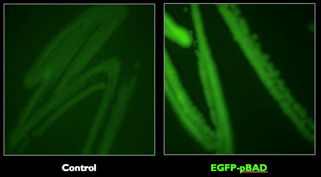
Figure 3. E. coli strains expressing the EGFP-pBAD was confirmed to fluoresce with the expected excitation and emission maxima at 488 nm and 507 nm, respectively.
Physical representation of the example gene:
The biological requirements for the different genetic building blocks for Arabinose inducible Fluorescence protein gene construct were defined. Once we defined the biological requirements, the software engineers, collaboratively with the biologists defined the software requirements for the blocks. These can be found in Table 1.


This step was allotted more time that we originally envisaged as it quickly became clear to all those involved that several discussions were needed to get acquainted with the languages of each discipline and decide how to translate the biological requirements into software requirements.
One specific discussion point was whether the output of a physical gene construct should come out of the coding sequence (cds) brick or whether the output should come out of the terminator block (T).
The electronics and software engineers would opt for the cds brick because this block encodes the functional protein. However, the biologists argued for the output to come out of the terminator sequence as only if all these blocks (including the 3’UTR and Terminator) are correctly assembled will there be an output signal.
The team then progressed to use match boxes to create a physical representation of the bio bricks in order for everyone to understand the biobricks and requirements for each of these (Figure 5).

Figure 5. Matchboxes are used to represent the gene construct

Figure 4. Sketch depicting the software engineer’s interpretation of output signal coming from the cds block.
Bio brick electronics design considerations
To help make a decision on electronics design, a couple of existing systems were bought to analyse how they work and whether a similar design would be suitable for the purpose of building the plug and play genetic system.
The electronics and computing will be distributed in three places:

Figure 6. Makeblock Neuron Inventor kit with programmable electronics and a touchboard
Within each bio brick a relatively low power memory or microcontroller, primarily they report a number or text identifier indicating which biological component they represent. Some intelligence is required so that these values can be programmed for each brick, and to identify themselves at the correct time so that the overall biological circuit can be deduced.
A user interface PC, smartphone, or Beaglebone (or similar controller board with sufficient computing power) and LCD display, which device will present text or graphic report on the modelled biological circuit, highlight biology errors and predict the behaviour.
A coordinating block that interfaces between [2] and [3]. This will connect to the bricks [1] to enumerate (~a roll call) which bricks are connected to the circuit, in what relative placements, and report over USB, Bluetooth or maybe a custom connection to [2]. This block would distribute electrical power to the bricks [1], perhaps from a battery. Note that this may be integrated with [2] in some of implementations considered.
For the first iteration the plan is to keep the design simple with microcontroller in each bio brick, the user interface software running on a (laptop) PC and communications and power between it and the coordinating block being combined in a USB connection. Ultimately it would be nice to operate with a smartphone, using a Bluetooth radio link, and probably using a rechargeable mobile phone battery (with connection & electronics to work with a compatible charger). [Footnotes a & b.]
For the initial prototype the concept is to put the 'dumb' units [1] inside each brick, have connectors on either end of all/most bricks so that the blocks can be assembled in a chain of bricks. (Missing connections could help guide the user to put together valid assemblies.) The connector will carry 4 or 5 active connections, 2 wires distributing 0V & 5V power, 2 or 3 wires distributing a communication link and controlling so that only one brick communicates at a time. The coordinating block [3] controls the enumeration of the bricks, and produces a map of their connections for the user interface component to assess. A number of connectors can be considered for prototyping to demonstrate the proof of concept, but developing a reusable, robust and reliable connector may need mechanical engineering support.
Other concepts were discussed, and could be tried in a second iteration:
Use of RFID tag technology, similar to that used in access cards for building security. All such devices have a 'unique' (within a system) serial number, some of them have a small amount of memory which could be set to a number or text which bio brick they represent. The tags, perhaps in their sticker form, could be placed in each bio brick. The RFID bio bricks could be used with a rollable mat (or rigid board) with a grid of RFID readers, to identify the relative positioning of the bio bricks. This sidesteps this issues with connecting the bricks together, at the tradeoff of complicating the coordinating block to control a number RFID coils. [Footnote c.]
Use of a 'breadboard', a rigid board with a grid of connections into which the bio bricks are plugged & unplugged. This could be between A4 and A3 sizes, and there may be a printed guide on the board to help younger students assemble a valid biological circuit, maybe a little like the children's game Operation. One realisation could use USB sockets for the bricks to plug into, with a USB hub under the board powering the USB ports. Each bio brick would have a microcontroller that connects to USB, it wouldn't to do much beyond identify itself as a USB device with the name of the brick's biological function as the device name. The coordinating block would then just use standard USB management function to identify the arrival & removal of the bio brick at each USB port.
Footnotes:
a. Official and third party mobile phone batteries for many brands of phone, e.g. from Amazon. Part selection would be through criteria such as output voltage, simplicity of the charging circuit, wide availability of replacements.
b. Bluetooth tested & approved radio sub-assemblies are available for less than £10, e.g. https://www.hobbytronics.co.uk/bluetooth-module-v2
c. A rollable RFID sensing mat would be straightforward to develop when we have the Biomakespace prototype lab available for electronics construction and testing. A similar mat was demonstrated in 2013 by CastAR (an ambitous Augmented Reality system that ran out of development funding in 2017), video here https://www.youtube.com/watch?v=IJrXf6waoUI
Follow on Plans
Despite the setbacks in opening the Biomakespace and therefore delay in the development of the hardware and lab based resources, this has not tempered the enthusiasm and commitment of the team to develop the resources.
To create the biological building blocks that will be used in future workshops to construct the simple reporter gene sequence example, we will organise a workshop at Biomakespace on the topic of golden gate cloning and primer design to create gene constructs. We will engage our first Biomakespace members to help us design the primers and also amplify the individual genetic sequences for the promotor, 5’UTR, cds, 3’UTR and Terminator. These sequences will then be individually inserted in plasmids and will be our biomakespace building blocks to create our example inducible gene.
Biomakespace is currently open to membership and the first projects (including Plug and play synthetic biology educational resource) have started.

Figure 7. The biology lab of Biomakespace
To build the Physical hardware/electronics component of the project, we have already called out to the makespace community to help us with the design of the electronics. With the prototyping lab at Biomakespace expected to be operational by April, we’re confident that we will create a larger team that will join in the development of the hardware.
We will soon be inviting Norwich biomaker community and London Biohackspace to visit Biomakespace and will use that opportunity to discuss the status of the plug and play system and discuss further collaboration on developing and testing of resources.
We will use the remaining funding for the activities above and in line with the project budget proposal.

Figure 8. The prototype lab in December 2018 (left) and February 2018 (right)
