
Water Level Sensor
Summary
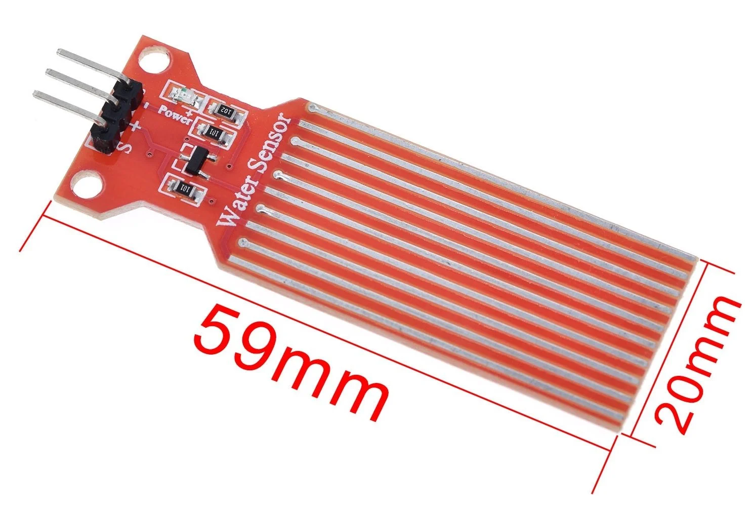
The water level sensor / leak detection sensor is a 3-pin module that outputs an analogue signal (generally 0 to 500) that indicates the approximate depth of water submersion. When used in conjunction with a pull up resistor, it can be used as a digital device to indicate the presence or water.
The sensor has a series of ten exposed copper traces, five of which are power traces and five are sense traces. These traces are interlaced so that there is one sense trace between every two power traces. Usually these traces are not connected but are bridged by water when submerged.
The series of exposed parallel conductors, together acts as a variable resistor (just like a potentiometer) whose resistance varies according to the water level. The change in resistance corresponds to the distance from the top of the sensor to the surface of the water. The resistance is inversely proportional to the height of the water:
The more water the sensor is immersed in, results in better conductivity and will result in a lower resistance.
The less water the sensor is immersed in, results in poor conductivity and will result in a higher resistance.
The sensor produces an output voltage according to the resistance, which by measuring we can determine the water level.
(Thank you to https://lastminuteengineers.com for much of the information on this page)
Tech Specs for the Water Level Sensor module:
Operating Voltage: +5V
Working Current : <20mA
Sensor Type : Analog or Digital
Water Detection Area :. 1.58in X .63in (40mm X 16mm)
Mounting Hole Size : 0.12in (3mm)
Operating Humidity: 10% to 90% (non-condensing)
Working Temperature: (-30 to 50 degrees C)

How to Connect
To connect to the Grove board:
The 3 pins in the module are:
S (Signal) pin is an analog output that will be connected to one of the analog inputs on your Arduino.
+ (VCC) pin supplies power for the sensor. It is recommended that the sensor be powered with 3.3V – 5V. Please note that the analog output will vary depending on what voltage is provided for the sensor.
– (GND) is a ground connection.
First you need to supply power to the sensor. For that you can connect the + (VCC) pin on the module to 5V on the Arduino and – (GND) pin to ground.
However, one issue with these sensors is their short lifespan when exposed to a moist environment. Having power applied to the probe constantly speeds the rate of corrosion significantly. To overcome this, we recommend that you do not power the sensor constantly, but power it only when you take the readings. An easy way to accomplish this is to connect the VCC pin to a digital pin of an Arduino and set it to HIGH or LOW as per your requirement.
Finally, connect the S (Signal) pin to a suitable unused analogue pin on the Arduino board.
How to use in XOD
Use analog-sensor node from xod/common-hardware library.
Values can be read repeatably from the analogue port at a suitable interval and used for calibration, display or further calculations. If a digital port is being used to power the sensor (to allow intermittent powering of the device, and minimise electrolytic corrosion) - the relevant port can be turned on, and a delay of >10 mSec added before reading the sensor and turning off the digital port again.


Test patch:
Set port to D2 (or whichever port you are using) and UPD to ‘Continuously’. Connect SIG to a watch node. Upload and debug.
Calibration
To get accurate readings out of your water level sensor, it is recommended that you first calibrate it for the particular type of water that you plan to monitor. Pure water is not conductive, minerals and impurities in water make it conductive. So, your sensor may be more or less sensitive depending on the type of water you use.
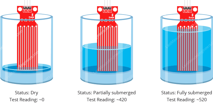
Before you start storing data or triggering events, you should see what readings you are actually getting from your sensor. Note what values your sensor outputs when the sensor is completely dry -vs- when it is partially submerged in the water -vs- when it is completely submerged.
In the example below, you see the following values in the serial monitor when the sensor is dry (0) and when it is partially submerged in the water (~420) and when it is completely submerged (~520). With a series of measurements, it is possible to draw a calibration curve that allows prediction of the precise physical depth of the water.
Notes
Water sensor hookup: https://www.hackster.io/NewMC/water-level-monitor-b42be9
How it works and interfacing with Arduino: https://lastminuteengineers.com/water-level-sensor-arduino-tutorial/
Water level sensor tutorial: https://www.thegeekpub.com/236571/arduino-water-level-sensor-tutorial/
Technical Specs
Click to download datasheet