
VL6180X Laser Range Finder (micro LIDAR) - 10cm range
Summary
The VL6180X is a I2C is a Time of Flight distance sensor. That means it uses the two I2C data/clock wires available on most microcontrollers, and can share those pins with other sensors as long as they don't have an address collision. The default I2C address is 0x29.
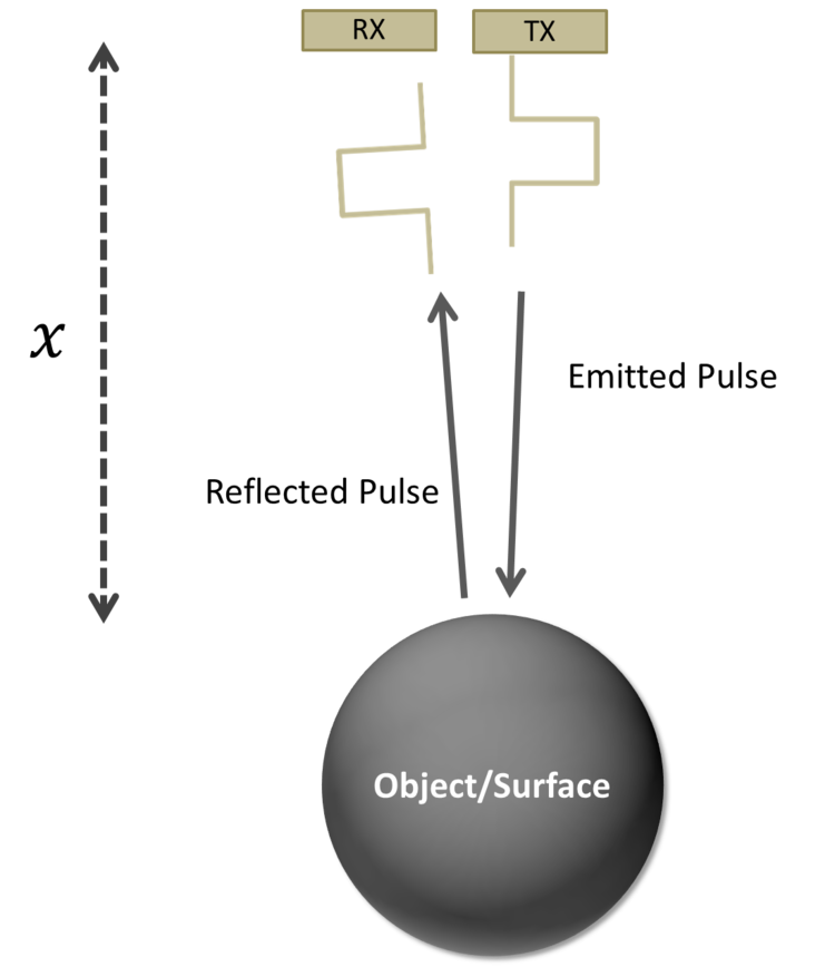
Many distance sensors rely on reflected light intensity or reflected angles to determine range. This sensor uses a precise clock to measure the time it takes light to bounce back from a surface. This is a great benefit over other methods because it can be much more accurate and more immune to noise. This sensor is commonly found in cellphones as the sensor that detects when the caller is holding their phone to their ear.
The integrated devices contains 850nm VCSEL solid state lasers, silicon photo avalanche diode (SPAD) detectors, ambient light sensors with a sensitivity < 1 Lux up to 100 kLux, 16-bit output and 8 manual gain settings, and accurate timing circuits to make time-of-flight measurements. The device is one of a family that an be used for different ranges. The VL6180X can handle about 5mm to 100mm of range distance, up to 150-200mm with good ambient conditions. For longer ranges, other devices, such as the VL53L1X can reach out to 4 metres. The devices are capable of relatively high sample rates of 20-50 Hz.
See https://makersportal.com/blog/2019/4/10/arduino-vl53l1x-time-of-flight-distance-measurement for more information about ToF measurements.
How to Connect
The sensor board has several plated holes for soldering standard 0.1” spaced pin headers.
Vin - this is the power pin. The chip uses 2.8V, and the board includes a voltage regulator on board that will take 3-5VDC and safely convert it down. To power the board, give it the same power as the logic level of your microcontroller - e.g. for a 5V micro like Arduino, use 5V.
GND - common ground for power and logic
SCL - I2C clock pin, connect to your microcontrollers I2C clock line.
SDA - I2C data pin, connect to your microcontrollers I2C data line.
GPIO - this is a pin that is used by the sensor to indicate that data is ready. It's useful for when doing continuous sensing. Note there is no level shifting on this pin, you may not be able to read the 2.8V-logic-level voltage on a 5V microcontroller (we could on an arduino UNO but no promises). Our library doesn't make use of this pin but for advanced users, it's there!
XSHUT/SHDN - the shutdown pin for the sensor. By default it's pulled high. There's a level-shifting diode so you can use 3-5V logic on this pin. When the pin is pulled low, the sensor goes into shutdown mode.
To connect to the Grove board:
Connect four I2C pins to corresponding sockets on the central portion of the microcontroller board - either directly, or via the breadboard.
Connect the GND pin to GND
Connect the VCC (5v) to 5V
Connect the SDA pin to SDA
Connect the SCL pin to SCL
These are the only connections required for normal use on the I2C bus, if you require the device to be shutdown and turned on again (i.e reseting the I2C address), a suitable digital port can be connected to XSHUT/SHDN pin (port D3 is used in the example provided in the wayland/vl6180x-time-of-flight XOD library.
How to Use
In XOD:
Load the external library wayland/vl6180x-time-of-flight.
The library contains nodes that allow control of the sensor, readout and demonstration patches (right). The example1-test-sensor patch can be used to test the connecttion to the device. A second patch, example2-change-address, demonstrates how to change the I2C address of the device - the patch will change the address to 30h, from the default 29h. (Careful, you may need to reset the address back to the default if you run this patch).
The VL6180X device is a complex sensor that provides a number of parameters for control, such as gain control, and readouts for status, such as out-of-range distance or high light levels.
Test patch:
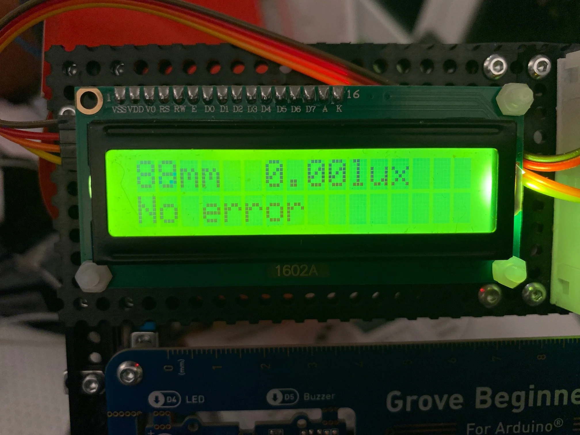
The tutorial file contains the patch 10-distance-tof-vl6180x. The patch takes readings for ambient light and measured distances from the sensor, and displays these on a connected 16x2 LCD display. It allows one to adjust the gain setting on the sensor, and formats the numerical output for display of sensor values and status.

Notes
How do vertical-cavity surface-emitting lasers (VCSEL) work? - https://www.sparkfun.com/news/2796 and https://en.wikipedia.org/wiki/Vertical-cavity_surface-emitting_laser
Excellent description of time-of-flight measurements: https://makersportal.com/blog/2019/4/10/arduino-vl53l1x-time-of-flight-distance-measurement
Technical Specs
VL6180X datasheet: https://cdn-learn.adafruit.com/assets/assets/000/037/608/original/VL6180X_datasheet.pdf
Explanation of VL6180X status codes: https://www.st.com/resource/en/design_tip/dt0020-vl6180x-range-status-error-codes-explanation-stmicroelectronics.pdf