
Infrared Pyroelectric Motion Sensor (HC-SR501)
Summary
The HC-SR501 sensor is a passive infrared (PIR) motion sensor which can be used to detect the occupancy and movement from the infrared radiated from a human or animal body. The passive infrared detector relies on receiving infrared radiation from the human body to trigger an alarm. The surface temperature of the human body is 36-27 ° C, and most of its radiant energy is concentrated in the wavelength range of 8-12 um.
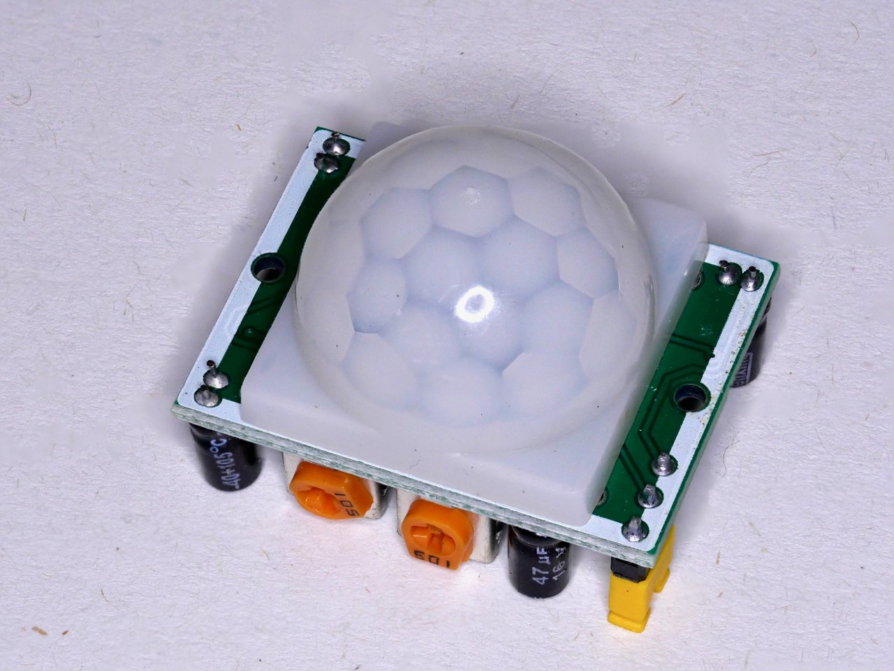
The white plastic cover is a fresnel lens to widen the angle of detection, and can be removed to see pyroelectric sensor underneath. The output of PIR motion detection sensor can be connected directly to one of the Arduino (or any microcontroller) digital pins. If any motion is detected by the sensor, this pin value will be set to “1”. The two potentiometers on the board allow you to adjust the sensitivity and delay time after detecting a movement.
The sensor properties are adjustable, and a switch and adjustable potentiometer are privided for this on the devices.
It has two modes Repeatable Trigger (H) and Single Trigger (Non-Repeatable)(L). H mode is the default. The mode can be set using the yellow jumper pins on the bottom side of the board. To switch to L mode, pull the yellow jumper shunt off the bottom two pins, and place it on the top two pins.
In Repeatable (H) mode, the sensor will send a high voltage when movement is detected within range, and will stay high for a set amount of time (T) before returning to low. The output will be the same whether the person is still in range or not. This sensor will reset the timer (which would otherwise turn the output off) each time motion is detected; this would be applicable, for example, for room occupancy lighting control where you don’t want the lights to blink off while the unit resets. In Non-Repeatable (L) mode, the sensor will go high when someone enters the range and will stay high until they leave the range.
The time parameter (T - for H mode) and sensitivity (S) can be adjusted using the orange potentiometer pins on the underside of the board, using a small flat-bladed screwdriver.
For proper calibration, there should not be any movement in front of the PIR sensor for up to 15 seconds (to allow self-calibration). After this period, the sensor has a snapshot of its viewing area and it can detect movements. When the PIR sensor detects a movement, the output will be HIGH, otherwise, it will be LOW.
Common applications include automatic house or garden light, burglar alarms, security cameras and motion detectors, tracking animal movements.

How to Connect
The sensor has three pins - VCC, OUT and GND (labels may be below the white plastic lens)
To connect to the Grove Beginner Kit board:
Choose an unused digital port (We are using either D2 or D10 in the examples below)
Connect three pins to the yellow coloured connector in the central portion of the board using Dupont jumper cables (this can be either a direct connection, or via the breadboard)
Follow the pin identifications shown directly above. (pin labels on the PIR sensor may be underneath the white plastic lens - you can lift the lens to check pin names and see the pyroelectric sensor)
Connect the Ground pin on the PIR module to a GND socket on the microcontroller connector
Connect the Power pin on the PIR module to a 5V socket on the microcontroller connector
Connect the Output pin on the PIR module to the chosen digital port socket on the microcontroller connector

How to use in XOD
Use the the digital-read node from the xod/gpio library. The SIG output pin will read ‘true’ if movement has been detected and ‘false’ if not.


Test patch 1 (right)
Set port to D2 (or whichever port you are using) and UPD to ‘Continuously’. Connect SIG to a watch node, or to an led node to get a visual output. Upload and debug.
Test patch 2 (below)
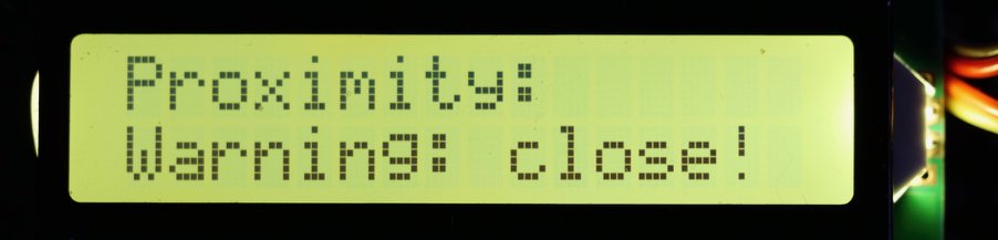
Here the PIR detector is connected to port D10. The status of the sensor (digital-read) is polled every 0.1 seconds, driven by pulses from the clock node. The output of the device is sent to a watch node and the on-board LED (led node). The PIR detector status is also sent to an if-else node. If the detector is triggered, the LED will light, and the true condition results in sending the “Warning: close” message to the LCD display via the text-lcd-i2c-16x2 node. A “Proximity:” label is displayed on the first line of the display.


Notes
How does a PIR motion sensor work? See: https://lastminuteengineers.com/pir-sensor-arduino-tutorial/
Working principle: https://robu.in/pir-sensor-working-principle/


Technical Specs
Wide range of input voltages varying from 4.5V to 20V (+5V recommended)
Output voltage is High/Low (3.3V TTL)
Can distinguish between object movement and human movement
Has to operating modes - Repeatable(H) and Non- Repeatable(H)
Cover distance of about 120° and 7 meters
Low power consumption of 65mA
Operating temperature from -20° to +80° Celsius
Delay time: 5-200S (can be adjusted, default 5s +-3%)
Blockade time: 2.5 S (default)
Mode adjustment: yellow jumper pin on underside of the board, pull up yellow jumper shunt and place over bottom to pins for H mode and top two pins for L mode, H is default
Sensitivity adjustment: orange potentiometer screw next to mode pins, switch between 3-7 meters, CW to high anti-CW to low
Time adjustment: orange potentiometer screw further away from mode pins, switch between 3 sec - 5 min, CW to long anti-CW to short