
12 x RGB LED Clock Face (WS2812 Ring)
Summary
This LED Ring contains 12 addressable WS2812B RGB LEDs (Red-Gereen-Blue Light Emitting Diodes), which can each be programmed from the microcontroller. The LED ring provide illumination required in machine vision, biomedical, fluorescence, and strobing applications - or be used as a vivid indicator or alert for sensors and logic programs. The use of 12 LEDs allows it to closely mimic a clock face.
It only requires 3 connections for the 12 LEDs (VCC (5V), GND (ground) and DI - data ‘in’ pin). Data for LEDs is sent in serial, 24 bit for each LED, representing 8 bit for the red, green and blue LED housed in each device. The controller contains a 24-bit register, which takes in serial data from the DIN pin and stores and decodes and displays it on the respective LED.
The 24-bit register is divided into three parts, each one is 8 bits long and holds a different brightness value for each color. Since there are 8 bits, there can be 256 possible brightness values for each LED. As there are three colors, a total of close to 17 million colors are possible.
The data pins on the LED are designed to be daisy-chained; the output of each device’s controller is buffered to maintain signal quality even if many LEDs are connected.


How to Connect
Requires access to a soldering iron.
The RGB LEDs are connected in serial fashion, and each has a particular position in the linear sequence. The microcontroller can communicate with each and all LEDs in sequence. In addition, LED rings (or other LED sticks or arrays) can be daisy-chained to build interconnected LED sequences. Each LED is individually addressable via serial digital communication that is passed into the ring via the DI (Digital In) pin, and can be passed through to another device via the DO (Digital Out) pin. If we are using the ring as a solitary device, we don’t need to use the DO pin.
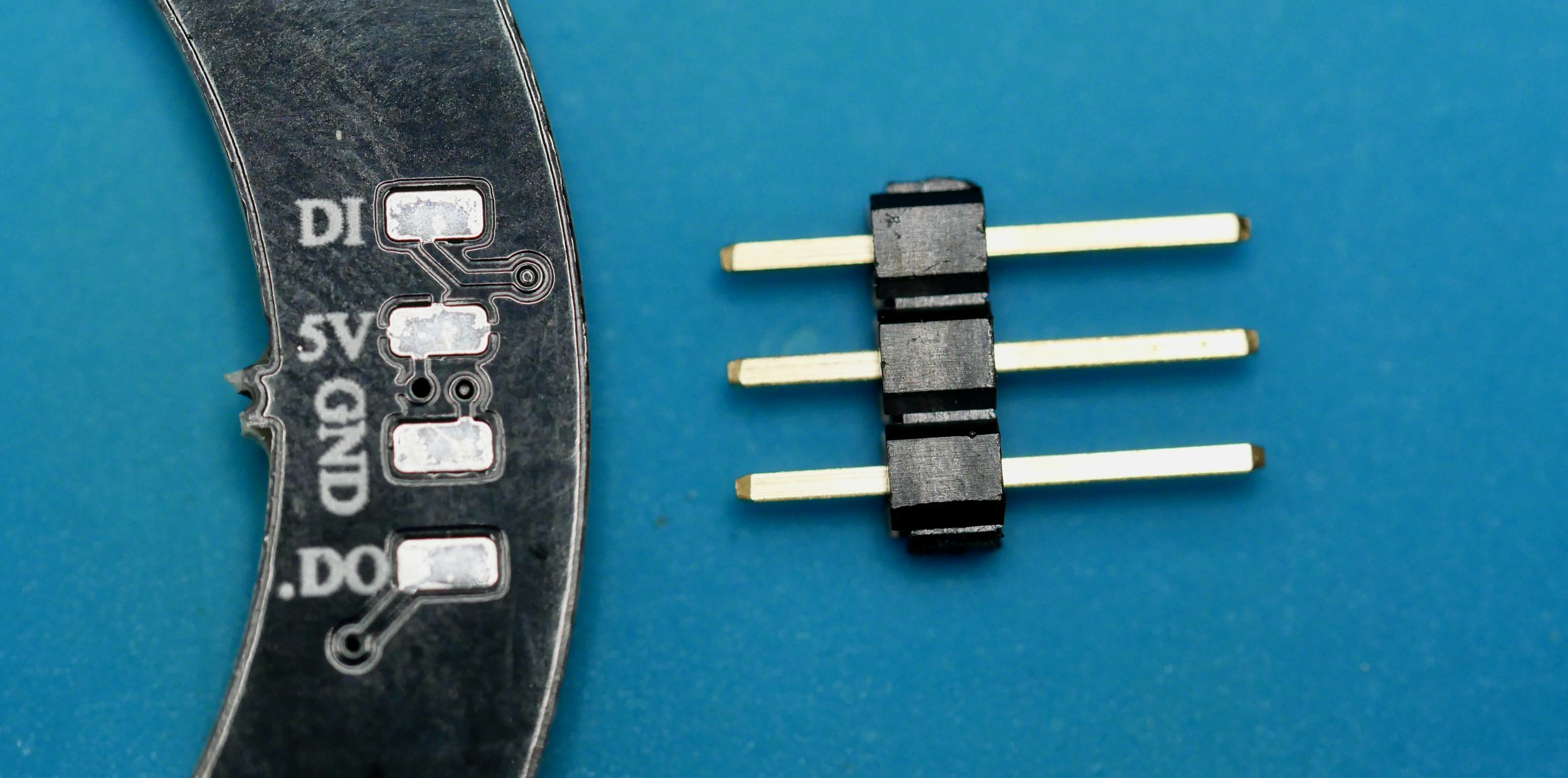
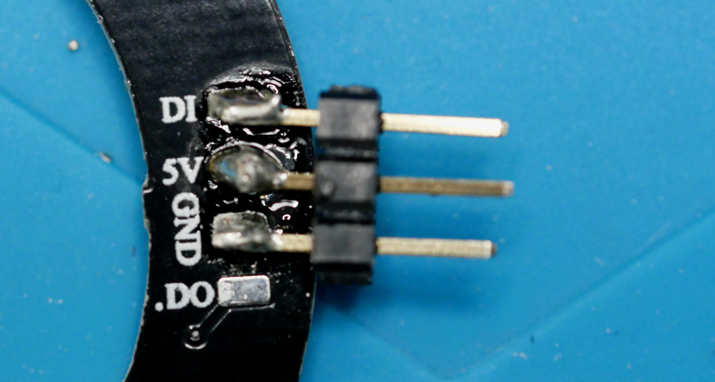
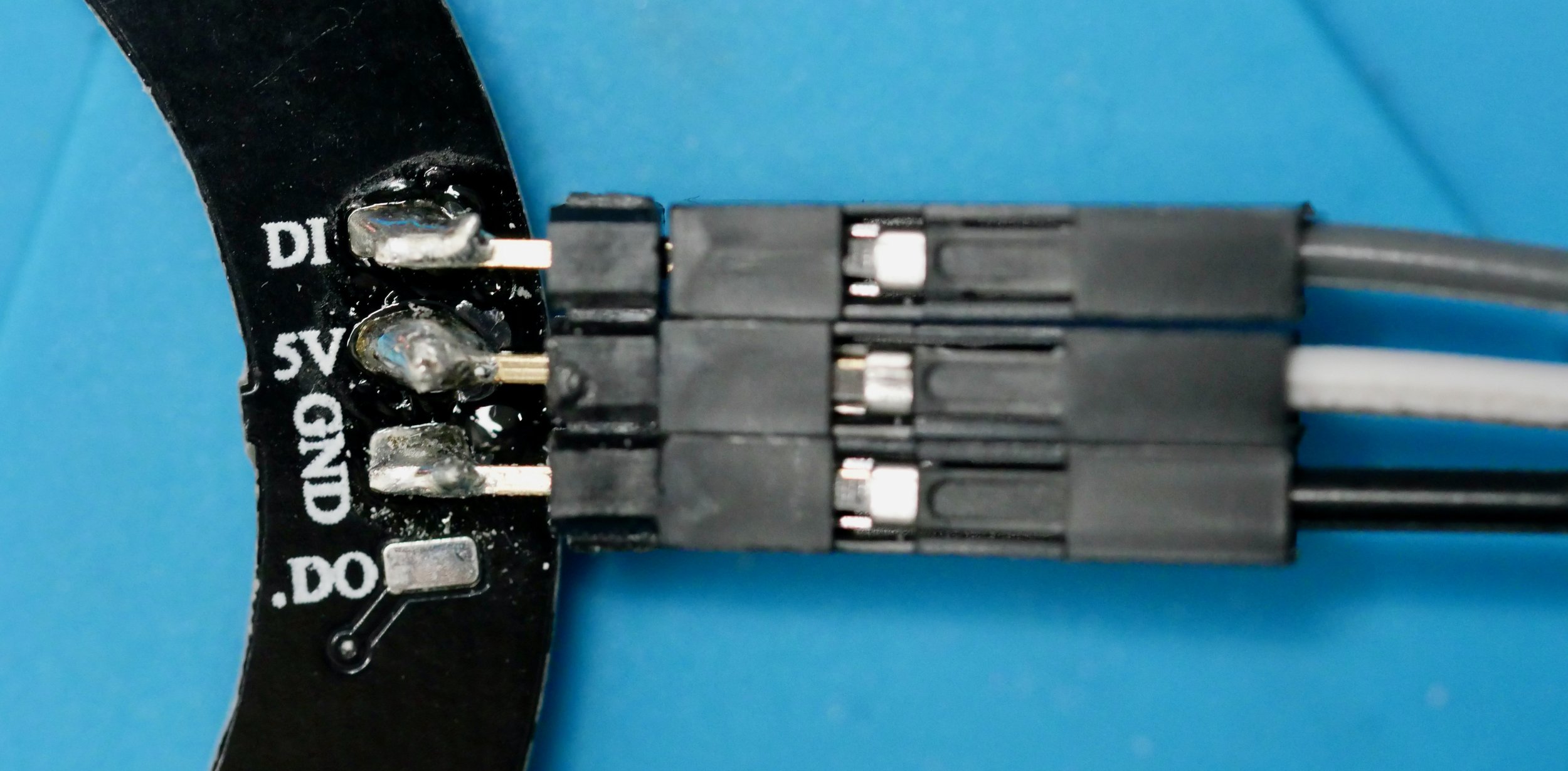
In order to connect the LED ring to the microcontroller, we need to connect leads to the DI pad and supply power through the 5V and GND (ground) pads. This can be done by directly soldering wire leads to the relevant pads, or soldering pins, that allow connection via socketed Dupont leads (shown right).
To connect to the Grove board:
Select an unused digital port on the microcontroller and connect this to the DI port of the LED ring, either directly or via the breadboard.
Connect the ground (GND) pin to a ground socket on the microcontroller board, either directly or via the breadboard.
Connect the 5V (Vcc) pin to a 5V source on the microcontroller board, either directly or via the breadboard.
Note: the LED ring is powered via the 5V supply from the microcontroller board, which is in turn usually powered through a USB port on a laptop or equivalent. If you notice erratic behaviour or unexpected resets - this may be due to excessive current draw. Each LED can draw up to 50mA at 5V and full light intensity. Also, the LEDs are bright and sometimes dazzling to work with. You can lower the emitted intensities (and current draw) of the LEDs by altering values in the software.
How to use in XOD
The standard XOD library xod-dev/ws2812 can be used to control the addressable RGB LEDs in the supplied hardware. The library contains a number of useful nodes, including the ability to flood all of the LEDs with a single chosen colour (ws2812-mono), to define a pattern or sequence of colour and to fill particular LEDs with this, or to address individual LEDs. The XOD nodes provide code to handle all of the complicated timing and signals to the LED devices.
Two examples are shown below. Both assume that the RGB LED ring contains 12 LED elements and is connected via D10.
The first floods all LEDs with the same colour, using the Grove Beginner Kit button to switch the LEDs on and off, and the potentiometer to control the hue of the emitted light. It also converts the HSL colour to RGB values using one of the standard XOD nodes (to-rgb), and displays the value on the LCD display, assuming it is connected.
The second example shows the definition of a static pattern consisting of a rainbow sequence of colours, set by constant values. Each can be set using the in-built XOD colour picker. The potentiometer on the Grove Beginner Kit is used to set a start location for the pattern, ranging from position 0 to12 (i.e. all around the clock face, back to the start).
There are more examples provided in the xod-dev/ws2812 library to allow some experimentation.
Further, there is a tutorial on how to use a neopixel ring in the Biomaker 2019/20 Handbook - Chapter 6: Handling Simple Input Output Devices. You can download the tutorial file to work through the task (patches tuto214-216).

Example 1
Example 2
Technical Specs
WS2812: guide to controlling NeoPixel RGB LEDs in XOD: https://xod.io/docs/guide/ws2812-neopixel/